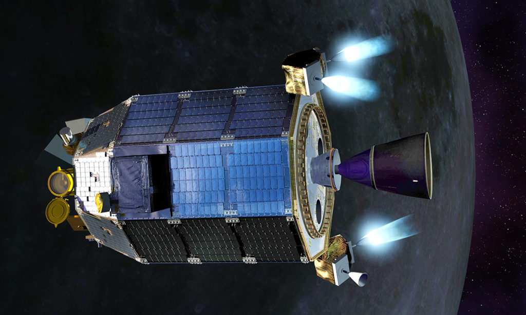
Human beings are curious about everything that’s happening in the world at all times. Satellites play a big role when it comes to sharing and accessing information worldwide. In the media, we hear a lot of buzz around the global applications of satellites but have you ever wondered how a satellite propulsion system is modelled? Most aerospace engineers will say “yes, of course”.
Now, the question is: do you know how to model satellites the “Valispace way”? We’ll show you how.
This tutorial will allow you to better understand the design process and create your own similar satellite subsystem in Valispace. Design of the propulsion system has various approaches but they all utilize the basic Tsiolkovsky rocket equation. The goal is, for example, to aid the satellite in monitoring ocean wavefronts and measure low altitude oceanic winds.
The key requirements for the design of any space propulsion system are:
- Satellite timeline and lifespan.
- Orbit to which the satellite will be launched.
- Mass of the payload.
- Cost of the systems and the technology readiness level.
Design Process
Mission Delta V
Mission DeltaV is the measure of the impulse per unit of spacecraft mass that is needed to perform a manoeuvre such as launch from or landing on a planet or moon or in-space manoeuvres. DeltaV is a budgeting parameter with which we decide the total quantity of propellant required for the mission.
ΔVTotal = ΔVinclination + ΔVRAAN + ΔVstation keeping +ΔVAOCS + ΔV de-orbit
Inclination Manoeuver
Inclination Manoeuvre is a spacecraft manoeuvre performed when the spacecraft has to remain in the same orbital altitude but on a different orbital plane, it is generally calculated from a vectorial geometric formula based on the fact that both the orbits will have the same orbital velocity and the manoeuvre occurs at the point of intersection of the two orbits (where V= orbital velocity, μ = GM = gravitational parameter, H = orbital height and Δi = inclination change).
The inclination angle change depends on the mission.
ΔV=2∗V∗sin(Δi/2)ΔV=2∗V∗sin(Δi/2)
V=√(μRe+H)V=(μRe+H)
RAAN Manoeuvre
RAAN manoeuvre is the transfer from a reference direction of the initial orbit (reference to the planets’ origin of longitude) to the direction of the ascending node of the transfer orbit. As a result, both orbits don’t intersect at the original RAAN location (where ΔΩ= Raan angle change).
ΔV=((π2)∗(√(μRe+H)∗Δ Ω∗sin(i)))ΔV=((π2)∗((μRe+H)∗Δ Ω∗sin(i)))
Station keeping Changes
Station keeping Changes in certain parameters related to sun, earth and moon cause a deviation in the orbital stability of the satellite which is exactly why we need to consider them. Usually, Earth’s Gravity, oblateness of the Earth, Atmospheric Drag, Solar Radiation Pressure and many more vary with time leading to general perturbation in the orbit.
Values are usually between 1-45 m/s per year depending on the satellite orbital height.
AOCS Manoeuvre
AOCS manoeuvre when certain small specific mission-related manoeuvring is performed. This is a priority when orbital manoeuvres are expensive comparatively.
Mission parameters
These are the parameters which help us design the subsystems of the propulsion system in a way that it abides by the mission requirements. To begin with, let us consider one of the propellants with a good range of Isp.
Hypergolic propellants are fuels and oxidizers that ignite spontaneously on contact with each other and require no ignition source. One of them is Hydrazine as it is frequently used as a monopropellant in catalytic decomposition engines where liquid fuel decomposes into hot gas (either hydrogen and nitrogen, or ammonia and nitrogen) in the presence of a catalyst.
Characteristic Velocity Vc
This parameter defines the combustion performance of the thruster based on the propellant type.
Vc=√((2kk−1)∗(RTM)∗(1−(PePc))k−1k)Vc=((2kk−1)∗(RTM)∗(1−(PePc))k−1k)
where R = ideal gas constant 8.3145 N*m/mol/K, T = combustion chamber temperature (usually 2773.15 to 3873.15 K), M = Molar mass =10.3 g/mol (with respect to hydrazine), Pc = Chamber pressure (usually 2 to 250 atmospheres).
Pe = pressure at the engine exit= 0.986923 atmospheres (approximately 1 atmosphere in Vacuum) and k = specific heat ratio (Cp/Cv)
Force coefficient Cf
This is another important parameter using which we can calculate exhaust velocity.
Where Ae = Nozzle area at the exit, At = Throat area and Pa = atmospheric pressure.
(Area ratio is usually between 2-6)
Cf=√((2k2k−1)∗(2k+1)k+1k−1∗(1−(PePc))k−1k)+Pe−PaPc∗AeAtCf=((2k2k−1)∗(2k+1)k+1k−1∗(1−(PePc))k−1k)+Pe−PaPc∗AeAt
Exhaust Velocity Ve
This parameter influences a few system requirements like effective exhaust velocity and thrust helps in reconfirming whether the thruster can produce enough thrust as per the mission.
Ve = Cf *Vc
Specific Impulse Isp
It is a measure of how effectively a rocket uses propellant. A propulsion system with a higher specific impulse uses the mass of the propellant more efficiently. This parameter is driven from the characteristic velocity and the force coefficient parameters discussed ahead (where go is the gravitational acceleration – 9.806 m/s^2).
Ve = Isp*go
Thrust
It’s the force that drives the rocket up into space (where q = rate of the ejected mass flow, usually ranges between 0.1= 0.5 g/s).
T=(qVe)+ (Pe-Pa)*Ae
The product qVe is the actual momentum and (Pe-Pa)*Ae is called the pressure thrust. It is a known fact that maximum thrust is obtained when Pe = Pa.
Are you brimming with excitement about what’s next?
We will show you how these calculated parameters will help in modelling the Thruster, Electronic Pressure Regulator, Pressurant Tank, Flow control Unit and others.
Part II is coming next week!
If you would like us to cover other space-related topics, feel free to reach out to engineering@valispace.com.
Thank you for reading.
References
Space Mission Analysis and Design (SMAD), 3rd Ed., James R. Wertz and Wiley J. Larson (1999)12:48 PM
Spaceflight Dynamics(3rd ED), Willan E Wiesel 2010
Image Source: NASA Ames / Dana Berry
